On the Topic of Process and Documentation by Maksym Prykhodko

Intro

Often times when I am working on a project, I contemplate not only on the art itself, but specifically on the process and how I choose to document it. I feel that these two terms are inseparable and not only impact how I see and understand my own work, but how I choose to take on new projects.


Process

In regards to process, we can think about how we go about our work. What is the most efficient way to make something? Or more interestingly, what is the most inefficient way to make something? Process is important to me because it serves as a jumping-off point for the rest of my work, regardless of whether I have it figured out or not. It doesn’t matter what the work is, but if I can leech on to a process that I consciously foster, expand, contract, and filter, my pieces becomes much more refined and focused.

A good example of my personal process relates to laser cutting. I know how to do it and I understand the methodology behind it. However, at this point, part of the process of working with lasers is that I expect to fail. Every new laser-related project I pursue has this idea of trial and error, experimentation, burning wood, and setting fires automatically built-in. I think this keeps things realistic, which is important in a world of perfectionists who expect to do everything in one go (me included).

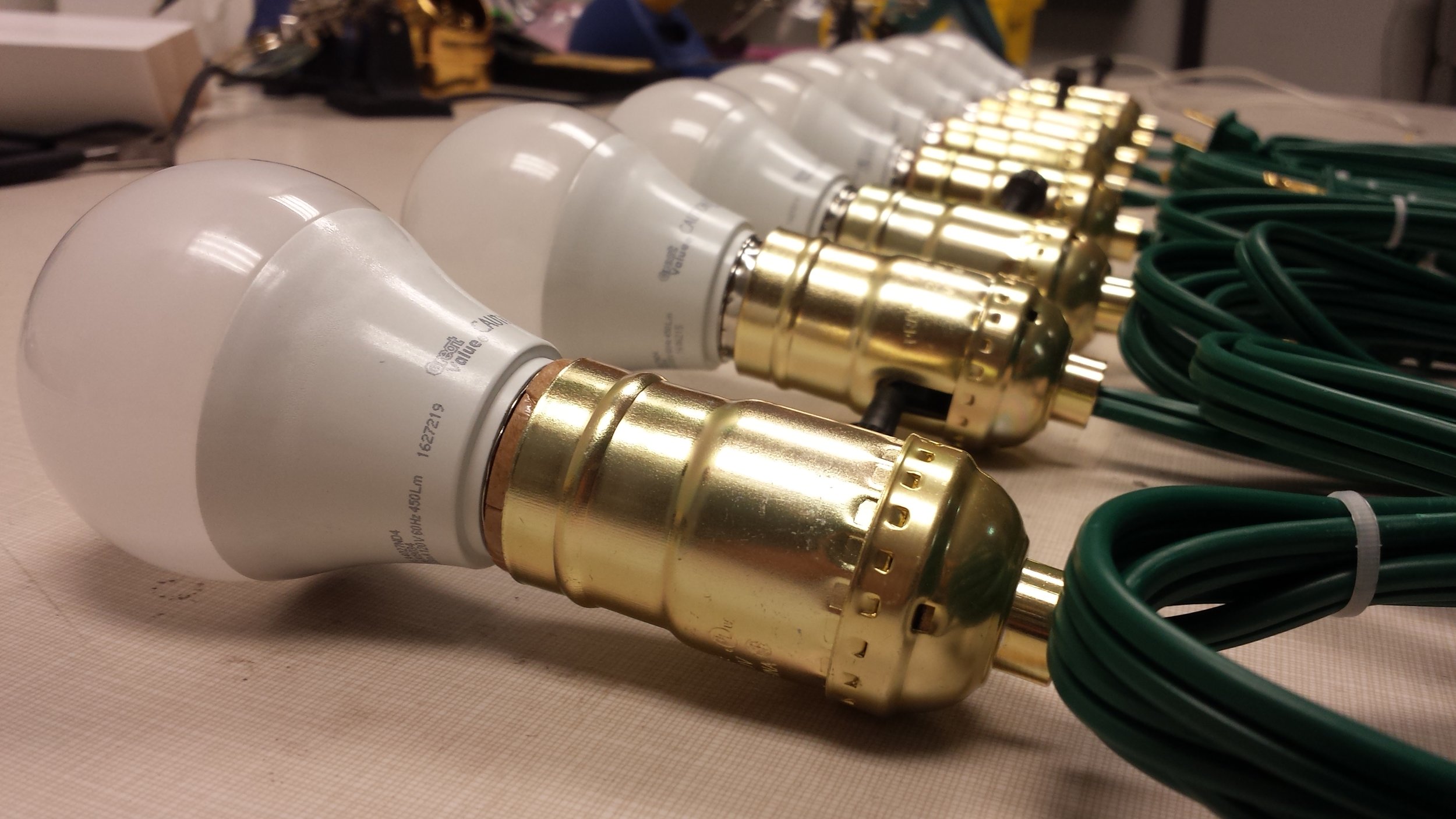
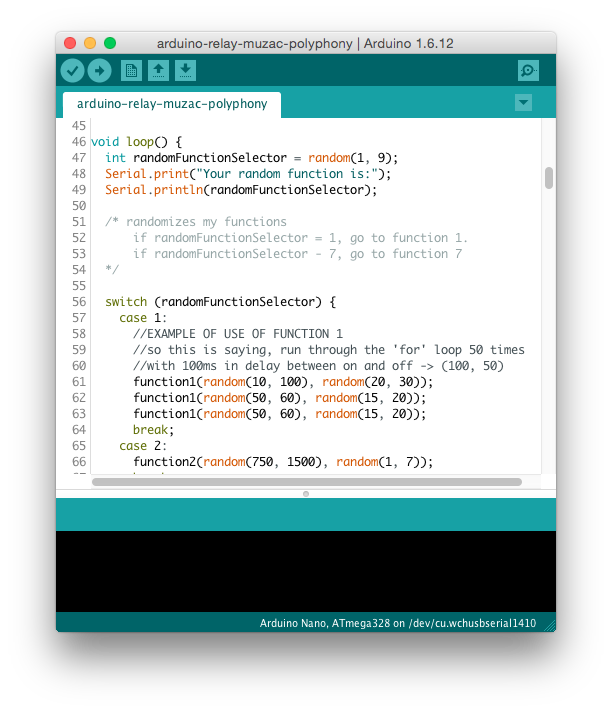
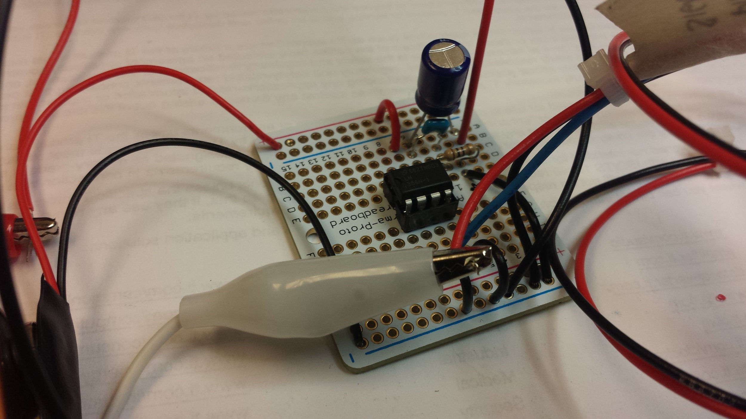
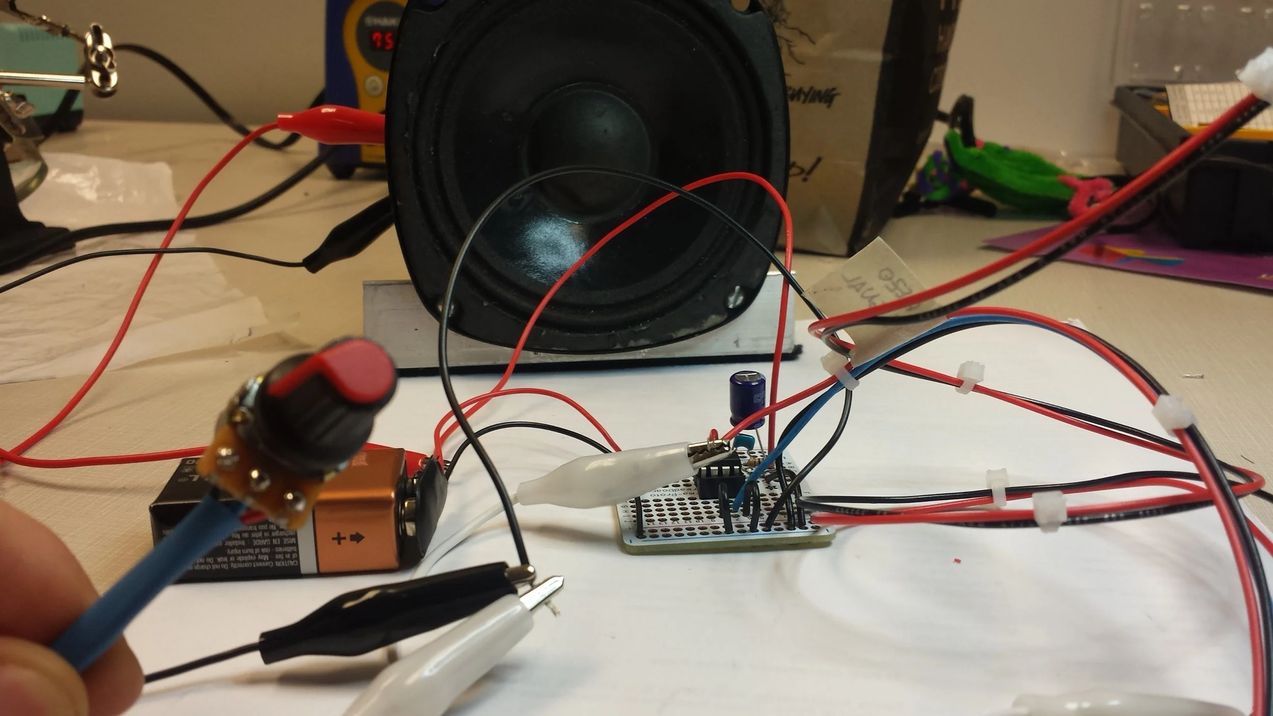
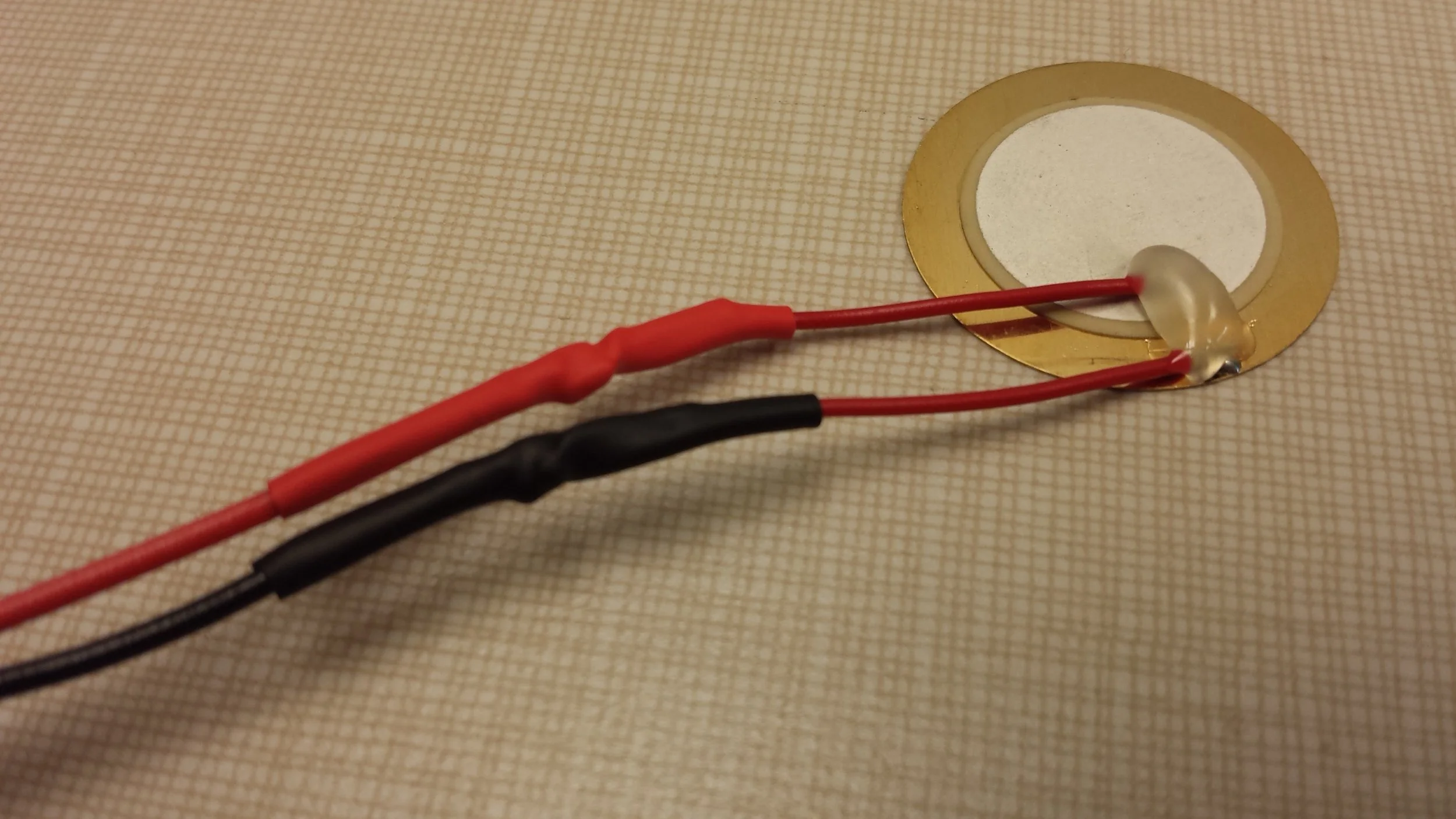
This idea of process can also be applied to my lightbulb installation shout. When I was invited to participate in Maker Faire Milwaukee 2017, I knew what I wanted to make, but I didn’t know what it would become. What I thought I made was an interactive installation in which sound waves were turned into light. What I didn’t realize was that I had absolutely no idea what it is that I made. I was too focused on hooking up wires and avoiding electrocution to consider in what way individuals would interact with the piece. I hadn’t figured out the core concept of the work until I actually witnessed the interaction.

People were meek, explosive, unpredictable even. All were initially taken aback and became either shy and disconnected, or totally embracing and vulnerable. The darkroom where my piece hung was surrounded with children of all ages, laughing, pointing, and most importantly experimenting. I learned in that moment that my piece was much more intimate than I had previously anticipated. It emphasized the novelty of experience as well as the novelty of surprise, exploration, vulnerability, and awe. In short, I learned about a kind of process of learning.

Experiences like these strongly alter my thought process regarding my work and force me to consider my art-making from a different perspective. They force me to embrace the unpredictability of interactive art, and perhaps embrace the void as it were. I don’t really know what will become of my work, and it doesn’t really matter. What’s important is that I have ideas that I explore, test, critique, and refine over time. Good ideas will last, while the terrible ones will die out. It’s natural selection at its core.


Documentation

Now, on the topic of documentation, I cannot emphasize how important it has been in shaping my thought process regarding my work. Everywhere I go, I have my phone, which means that any work that I am making has absolutely no excuse not to be documented and catalogued.

To be honest, I never started the act of documentation until fall of 2016 when I was in Pete Prodoehl's Electronics and Sculpture course (University of Wisconsin-Milwaukee). Not only was this the first time that I “officially” delved into interactive technology, but this was also the first time when I began to perform proper documentation of my art.

At some point I became obsessed with the process and now it has manifested in my every day activities, going so far as giving me a nervous twitch if I don’t pull out my phone and take a picture of the current in-progress piece. Regardless, the act of documentation itself serves a number of extraordinarily valuable roles:

  1. It serves as evidence of your work, and proves that it does indeed exist.

  2. It captures the step-by-step process, which is monumental in understanding how you made the work, how you think of it, and how you choose to go about it.

  3. It acts as a bookmark or time capsule, capturing your progress in this moment of time, one that you can always come back to.

  4. It provides an opportunity to share your creations with others, even going so far as teaching and instructing the process of art-making and what yours might be.

Keep in mind that documentation is not limited to photographs. I often times forget this, but it can manifest itself in videos, notes, sketches, models, Illustrator/Photoshop files, receipts, labels, spreadsheets, junk, spoiled food and moldy bread. Basically, anything that we can see/touch/hear/taste/feel from the inception to the end of your project all serves as precious evidence.

My own art has been shaped by the action of documentation because it forces me to consider my work as a series of steps. Though it’s a beaten down analogy, a kind of pyramid shape emerges as we travel from A to B to C, all the meanwhile building on top of the previous step and outlining our path. Indeed, this is exactly the definition of a process. This useful series of steps allows us to come back to an earlier iteration of our project, and allows us to try a different path. No regrets, only opportunity.

No, you can’t over-document, and yes, take extra photos because I promise you at least one or two will be blurry. Keep your camera charged up and always have a pencil and paper at an arms length away. If you get something to work, document it before it sets on fire. Remember: just like science, it didn’t happen unless you have evidence, so don’t miss the moment.

Relay Muzak by Maksym Prykhodko

Relay Muzak is an audio-visual composition focused on the idea of overstimulation. The blinking of the LED lightbulbs is sporadic and aims at diverting built-up expectations. The clicking of the relays are in many ways synonymous to the rumble of a film projector. It’s an added component that is not the main focus, but one that compliments the visual media.

The completed final project:

Uploaded by Maksym Prykhodko on 2016-12-20.


Gathering Materials

In order to build this project, I knew that I needed a few components:

  • LED lightbulbs (x8)
  • lightbulb sockets (x8)
  • extension cords (x16)
  • Arduino + connectors
  • Tools tools tools

Learning about Relays

In my Electronics and Sculpture class, I learned about something called a relay. Essentially a relay is a programmable on/off switch. Therefore, one could potentially connect a bunch of electronics to a bunch of relays, and use an Arduino to control which of them turn on and off. Imagine a light switch in your room that you can turn on and off at an incredible speed. The project was essentially this idea taken to the extreme.

I went online and bought myself an 8-channel relay from Adafruit

I went online and bought myself an 8-channel relay from Adafruit

I found a piece of wood in the back on which I could mount my 8-channel-relay on

I found a piece of wood in the back on which I could mount my 8-channel-relay on

One consideration I had was the kind of Arduino I should use to control the on/off rate. I began experimenting with an Arduino Nano, but in the end decided to go with the Uno instead as it had an input barrel jack.

4.jpg

At this point, I just simply wanted to test turning relay on and off to see how the thing actually functioned.

I took a lamp and plugged it into a spliced extension cord which was connected to one channel of the relay. The original lamp plug remained unscathed but the cheap extension cord gets transformed . More on this later.

I also found out that gaffers tape would be my friend throughout the project. I gaffed my connections to the piece of wood, and plugged everything in. Since I am dealing with AC current, it’s important to be careful.

5.jpg
6.jpg

A brief video showing my first experiment:

Uploaded by Maksym Prykhodko on 2016-12-20.

I began to experiment further with more sporadic patterns, and began to hook up more and more relay channels to my Arduino. 

I began to experiment further with more sporadic patterns, and began to hook up more and more relay channels to my Arduino. 

Since I had only one light at the time, you can only see its flashing yet still hear the clicking (turning on and off) of the other relays.

Uploaded by Maksym Prykhodko on 2016-12-20.


Creating the Lightbulbs

Now, it was time to purchase the main components for constructing my lights. I went to the local dollar store  and bought sixteen extension cords (eight to create the lightbulbs, and eight to create extensions from the lightbulbs to the relays). They were 6 feet each, and I felt that this was a good length to start with.

8.jpg

I also picked up eight lightbulb sockets. Note the off-color one at the bottom right of the photograph. I picked it up because the store I bought the others from ran out. However, it stood out like a sore thumb and generally looked distracting, so I eventually went back to the store when they restocked and bought another one.

9.jpg

The last items that I need were the actual lightbulbs. I spent some time thinking about whether I should get LED lightbulbs or incandescent. In the end, I decided to go with the LED because:

  • they were cheaper
  • lasted for a long time (many years)
  • didn’t get hot 
  • made out of plastic

As I went on with the project, I eventually realized that they are EXTREMELY advantageous and are able to be turned on and off VERY quickly. They are made of plastic which helps with my clumsy self and are overall an amazing purchase. Plus, they’re supposed to last me 9-18 years, so if anything, I have set up my living house with lights for the next 20 years.

10.jpg

Now, it was time to figure out how to wire up my extension cords to my lightbulb sockets. I read online that it’s a potential safety hazard if they were to be connected backwards, so I made sure to do plenty of research first. 

Here is my socket taken apart:

Here is my socket taken apart:

First, I had to grab my extension cord, and cut off the end with the multiple plug holes.

12.jpg
13.jpg

I then split the cord down the middle and stripped a bit of wire off each side.

14.jpg

I threaded the butt of the socket through the wire before I did anything else. It’s annoying figuring out that you forgot to thread it through after connections are made.

I discovered something called the underwriter’s knot. This is a knot essentially used as strain relief. If the cord were to ever get yanked, the wire won’t slip from the screws, severing the connection.

15.jpg

It was now time to hook up my prepared cord to my socket. However, how do I know which of the connections is hot and which is the neutral? Well I learned that the plug itself is a giveaway about what it sends. 

On the end of the plug, the wider prong is hot, and the narrower prong is neutral. At that point, you just have to follow that cord all the way from the plug up to the socket. The hot cord gets attached to the gold screw and the neutral to the appropriately cold and blue-ish screw. 

In the picture above, note how the cord on the right corresponds to the hot connection and the one on the left corresponds with the neutral.

In the picture above, note how the cord on the right corresponds to the hot connection and the one on the left corresponds with the neutral.

Now, I put the cover back on and sealed up the whole socket nicely.

17.jpg

I tested the lightbulb and was thrilled to see that it worked and that I wasn’t mortally electrocuted.

18.jpg
My first completed lightbulb!

My first completed lightbulb!

After doing this seven more times, I had my array of lightbulbs.

20.jpg

Connecting Lightbulbs to Relays

Now, it was time to connect the lightbulbs to the relays. These are the eight extra cords which are utilized as spliced extension cords for lights.

21.jpg

At about the halfway point, I cut one of the wires of two, and inserted eight of them into their own discreet relays.

Gaffers tape was absolutely necessary to take strain off the wires and to protect myself from electric shocks.

Gaffers tape was absolutely necessary to take strain off the wires and to protect myself from electric shocks.

After some time, I hooked all eight of them up to the relays, secured them with zip ties and gaffers tape, and organized the cords.

23.jpg
24.jpg

I then hooked up my Arduino to the relay.

25.jpg

I bought a power strip and a small plug splitter so that I could fit all eight of my AC lightbulbs.

26.jpg
27.jpg

Now, I plugged into the power strip and switched my Arduino on:

Uploaded by Maksym Prykhodko on 2016-12-20.

A success!


Setting up the Project in the Space

The last and most important step was to hang up my installation in the hallway. As a side note: the location is quite dark, so there is only so much that I can show you.

28.jpg

Since I wanted to have my lightbulbs hanging from the ceiling, I found a spot a little out of the way and on the side. I climbed up the ladder and took a closer look. I felt that this was the best place to mount my project. I got out the gaffers tape and after dusting, attached my circuit to the top of a fluorescent light.

29.jpg
I found a good way to secure the cords was to just tie them to the existing beam using a simple knot

I found a good way to secure the cords was to just tie them to the existing beam using a simple knot

31.jpg

Here was the result. I spread the lightbulbs as far apart as I could.

32.jpg

Since there was no AC power by my installed lights, I had to extend a cord (yellow) several feet from a plug towards my direction.

33.jpg

I then taped my power strip to the other end of the top of the light.

34.jpg

I found a nice little connector to power my Arduino using a 9 volt battery.

35.jpg

A little video of me running through the setup in the rafters:

Uploaded by Maksym Prykhodko on 2016-12-20.

Now, all was functioning correctly:

36.jpg

Side angle of my working lights:

Uploaded by Maksym Prykhodko on 2016-12-20.


A Note about the Code

I haven’t spoken about my code yet, but wanted to take a second to explain how it functioned. Essentially, the code exercises randomization within parameters. I took this opportunity to practice writing functions. I wrote eight functions. One function per relay. Each function was associated with how many relays were on at the same time. Function 5 = five random lightbulbs are chosen to turn on and off. Function 3 = three random lightbulbs are chosen to turn on and off.

I found that the best result was a balance between very quick gestures and slow ones. It’s the contrast that makes the piece effective and that helps the audience focus on both the visual and sonic aspect of the piece.

37.png

Takeaways and Future Improvements

In retrospect, I found that this project went surprisingly smoothly and I didn't really have to redo anything. There were difficulties, but I felt comfortable with them overall. However, I feel like if I had to redo the project, there would be some things that I would want to do differently:

  1. I wanted to have audience interaction. My initial idea was to have an instrument (like a synthesizer) on a pedestal that the audience could interact with. The flashing of the lights would be a response to the sound.
  2. Many individuals complained that the incessant flashing was a bit much. A diffuser would take the harshness of the light down, although it would go against the initial concept of the piece.
  3. I could have written the code better. Instead of having seven functions, I could have just one with three variables instead of two. Coding is something that I’m still working on and continuing to improve.
  4. If I ever wanted to create a version of this piece with inaudible clicking of the relays, I could use solid state relays. It's something to keep in the back of my mind.

In the end, I feel satisfied with this project and feel that I set realistic goals, was able to learn how to control high voltage AC using an Arduino and relays, and have had an opportunity to explore a new aspect for me in art making. 

Thanks for reading!


“Relay Muzak” is a comment on the idea of technology for human entertainment. The installation humanizes itself through a perceived character consisting solely of algorithms and randomization. It is simply plugs and code. However, it is through deception that it gains the steady trust of the audience, eventually breaking it completely. Consisting of eight lightbulbs, the sight is intense and bright to be sure, causing spectators to either quickly disappear in sickness or become absolutely entranced in the flashing bulbs.


Parasonic by Maksym Prykhodko

Parasonic is an interactive sculpture designed to envelop the listener in the noise of rain. The name is derived from the words "parasol" + "sonic." Essentially, this sculpture is an umbrella fitted with sensors, an amplifier, and a headphone jack. The listener is then able to plug in their own pair of headphones into the jack, and be cocooned in a sonic sheet as they walk around in the rain.

The piece is meant to be an isolating yet personal experience which allows individuals to amplify the common afterthought of rain. It speaks to the idea of a culture in which individuals quite literally disconnect themselves from the world through the use of headphones. It is a conscious and intentional separation from the bustling noisy soundscapes present in our environment. We can witness this on the bus, at our grocery stores, and especially at the local university campus. This piece is essentially a reversal of that idea while utilizing the same technology to do so. It is aimed at allowing humans to focus on external stimuli as opposed to the traditional internal ones.

Here is a brief video of the completed project:

Uploaded by Maksym Prykhodko on 2016-12-19.


Gathering Resources

To create this sculpture, I needed to gather the main components:

  • umbrella
  • amplifier
  • piezo disks
  • Plasti Dip
  • 1/8" female auxiliary jack
  • a generous collection of tools
I went to a local store and found a cheap little umbrella. It cost me $6.

I went to a local store and found a cheap little umbrella. It cost me $6.

Since this project is in many ways a prototype for my ideas, I wanted something relatively cheap. If I majorly screwed up my parasol, I had an pretty affordable way to get another one.

Since this project is in many ways a prototype for my ideas, I wanted something relatively cheap. If I majorly screwed up my parasol, I had an pretty affordable way to get another one.


Building and Testing the Amplifier

The next step involved acquiring an amplifier. Because I’m cheap and believe in building character, I decided it was worth building my own amplifier from scratch. Through sheer luck, I was able to find an Integrated Circuit called the LM386. Conveniently, the datasheet also contained a variety of schematics for building amplifiers with different levels of gain. This is the one I chose:

3.png

The list of components was relatively minimal, and the build of the amplifier was pretty easy. All I really needed to buy was the IC, and a board on which to mount it on. I already happened to have all the other parts.

I began by prototyping the amplifier on a breadboard to make sure it actually worked. I wanted to get a sense of how much amplification this little circuit could give me.

In the above picture, the little electrolyte capacitor actually provided me with a 200 gain boost. I decided to take it out later on and replace it with something smaller.

In the above picture, the little electrolyte capacitor actually provided me with a 200 gain boost. I decided to take it out later on and replace it with something smaller.

To simulate an umbrella, I took a piezo disk and taped it onto a sheet of plastic I cut out from a bag. I was pleased to hear the amplified crinkling through the speaker.

5.jpg

Here is a brief video explaining the circuit:

Uploaded by Maksym Prykhodko on 2016-12-03.

Here is a brief video of me testing the circuit with a piezo disk:

Uploaded by Maksym Prykhodko on 2016-12-03.

After I made sure that the circuit functioned properly, I decided to start building the final prototype of it. I ordered a set of three Adafruit Perma-Proto Half-sized Breadboard PCBs. I found this to be the best board to recreate the circuit on my breadboard as it was compact and had the familiar feel of a breadboard.

This was my work station where I did all of my soldering

This was my work station where I did all of my soldering

The helping hands and magnifying lens were essential so I could actually see what I was soldering. I wear glasses so every little bit of magnification saves strain on my eyes.

Here are some pictures taken throughout the build:

7.jpg
8.jpg
9.jpg
10.jpg

For the potentiometer (volume control), I decided to create an extension so I could eventually hot glue it to a part of the umbrella and run the wires along the stretcher (rods coming out of center) to the completed board.

Red = voltage in, Black = ground, Blue = control

Red = voltage in, Black = ground, Blue = control

12.jpg
13.jpg
I decided to add heat shrink tubing on the wires coming out of the potentiometer for extra security and snugness. To control the flow of wire, I added zip ties and attached it to the board shortly after.

I decided to add heat shrink tubing on the wires coming out of the potentiometer for extra security and snugness. To control the flow of wire, I added zip ties and attached it to the board shortly after.

Here is a picture of the completed circuit

Here is a picture of the completed circuit

Video of me testing the completed circuit:

Uploaded by Maksym Prykhodko on 2016-12-03.

I was happy to finally have the amplifier finished and working. This was actually the second time I had to build it. The first time is not pictured here. However, it turned out to be a complete nightmare. I tried to built it on some cheap boards with major difficulty, and in the end it wouldn't even work. Ah! The magic of working with electronics.


Piezo Sensors

The next step was to create my sensors for amplifying the rain. For those unfamiliar, speaking into a piezo disk will not produce any sound, but placing it against your voice box will. This is because it picks up vibrations. Because of this property it is often used as something called a contact microphone. I found four of them, and began to solder extension wires to them.

The two wires that run to the piezo are incredibly fragile, so reinforcement here was key.

The two wires that run to the piezo are incredibly fragile, so reinforcement here was key.

Hot glue between the two solder points also helped to prevent the ripping of wire

Hot glue between the two solder points also helped to prevent the ripping of wire

Heat shrink tubing around the wires helps to maintain the connection between the thicker and thinner wires.

Heat shrink tubing around the wires helps to maintain the connection between the thicker and thinner wires.

I figured that one more layer of heat shrink tubing was in order to strengthen the connection to its maximum extent. It's worth overdoing it early in the process than having to redo it all later on (spilled milk analogy).

I figured that one more layer of heat shrink tubing was in order to strengthen the connection to its maximum extent. It's worth overdoing it early in the process than having to redo it all later on (spilled milk analogy).

I went through the process four times and ended up with four sensors:

21.jpg

I acquired something called Plasti Dip at my local hardware store. Essentially, it is a coating most often used for protecting and weatherproofing tools. It helps avoid abrasion and is incredibly valuable to my project because it has the unique property of waterproofing items. This was the last step in strengthening my piezo disks.

To the company that manufactures Plasti Dip: if you see this and want to throw more of your products at me, you know how to reach me (maksymprykhodko.@gmail.com)

To the company that manufactures Plasti Dip: if you see this and want to throw more of your products at me, you know how to reach me (maksymprykhodko.@gmail.com)

At this point, I dipped my piezos in this substance, and let them dry by the air vents:

23.jpg
24.jpg

After they became tacky, I added a second coat. As a side note: according to the wonderful Nic Collins, three coats is usually too much. The Plasti Dip does deaden the sound, but luckily for us, that tends to be the shrill upper frequency range, so it’s not too much of a loss.

Much like the amplifier circuit, this was my second attempt at making piezos. The reason? I used the Plasti Dip spray the first time around, and it was simply not sufficient. Do you ever feel like you experienced deja vu? Here is a picture of one of the original unused piezos:

All of those bubbles are not receptive to waterproofing. This tells me that that method simply wasn’t good enough. Therefore, the second time around I invested in the actual dip.

All of those bubbles are not receptive to waterproofing. This tells me that that method simply wasn’t good enough. Therefore, the second time around I invested in the actual dip.

Compare the above photograph to one of the new-and-improved piezo disks. The entire surface of the disc is completely and utterly sealed. Have you ever made pelmeni? Well, my mom and I used to make them all the time in my youth. The story here …

Compare the above photograph to one of the new-and-improved piezo disks. The entire surface of the disc is completely and utterly sealed. Have you ever made pelmeni? Well, my mom and I used to make them all the time in my youth. The story here is the same: you gotta make sure the thing is sealed up before you toss it in the water.

I conducted some experiments with the previously unused piezos. Here is one of the videos:

Uploaded by Maksym Prykhodko on 2016-12-03.

Note: this was the previous version of the piezo and was NOT used in the final result of this project. However, I wanted to demonstrate how they reacted when amplifying water. The concept is exactly the same for these new sealed up sensors.


Connecting, Mounting, Soldering

Now that the creation and reinforcement of my sensors was complete, the last step was to combine all of my discreet items and mount them onto the parasol itself.

Before mounting and connecting of my parts, it was important to figure out where each one would be situated. I went ahead and planned my course of action, focusing on the skeleton of the umbrella as a significant structure which could be utilized to my advantage.

27.jpg
Here is the top of the umbrella. This is where the piezo disks would be threaded through to the underside.

Here is the top of the umbrella. This is where the piezo disks would be threaded through to the underside.

A view from the underside:

A view from the underside:

A compilation of photographs documenting the accumulation of piezo disks:

30.jpg
31.jpg
32.jpg

I put the original cap of the umbrella back on top. This proved to be incredibly helpful as it helped to keep the piezo disks in place.

33.jpg

Next, I routed all of the wires to one side of the umbrella. This was important in connecting the piezos to the amplifier.

34.jpg

Using zip ties, I secured the wires to the stretcher and the rib of the umbrella. The great thing about coming up with new projects is that it actively gives you an excuse to learn new stuff. Tell me, would you ever learn what the "rib" of an umbrella is in your everyday life?

35.jpg

I made sure that the umbrella was still closable. I was happy to see that it was.

36.jpg

A brief explanation of the build so far:

Uploaded by Maksym Prykhodko on 2016-12-07.

I put some thought into how I was actually going to attach the parts on the silky skin of the umbrella. I thought about sewing the piezos onto it, but ultimately decided against it. Instead, my go-to turned out to be hot glue. I was careful to apply it, but I think it turned out quite well.

Glued piezos to the top of the umbrella:

Glued piezos to the top of the umbrella:

Here is my female 1/8′’ jack. Note: red and white cords = left and right channels, thick cord = ground

Here is my female 1/8′’ jack. Note: red and white cords = left and right channels, thick cord = ground

I made sure to test this to make sure that I had “stereo” audio in my headphones. What is actually happening here is that I am connecting all of the piezo signals to a mono channel. This assures that all of them get amplified equally.

39.jpg

The connecting and soldering of all the piezo wires:

40.jpg
41.jpg
I made sure to shrink tube everything that I could. The less exposed the wires, the better. It is an umbrella after all.

I made sure to shrink tube everything that I could. The less exposed the wires, the better. It is an umbrella after all.

Finally, all my connections were complete.

43.jpg

A brief video explaining how I was going to mount my materials:

Uploaded by Maksym Prykhodko on 2016-12-09.

I zip tied the audio jack to the stretcher. I was careful to make sure the umbrella was still able to open and close.

44.jpg

I found a way to use zip ties to connect the 9v battery to one of the ribs. This proved to be a nondestructive way to do it. When the battery dies, I can always replace it with a new one without harming the umbrella.

45.jpg

Here I glued the board to the material of the umbrella. I made sure that there was enough reach between the battery clip and the battery.

46.jpg

Everything except the potentiometer was now attached to the umbrella.

47.jpg

Tragically, my potentiometer broke, so I replaced it with a better one. This one worked flawlessly. Once again, these are the happy little accidents that occur when working with electronics. No biggie.

48.jpg

The potentiometer wouldn’t fit snuggly on the black handle, so I found a bit of wood (which I filed endlessly) to mount the potentiometer on. The wood then fit on the handle.

49.jpg
50.jpg
51.jpg

At last, all was mounted and connected.

52.jpg
53.jpg

Now that everything was completed, the final step was to test whether this device actually worked. When I plugged headphones into the jack, I was pleased to hear the amplified and explosive rattling of the handle as I twisted and turned the parasol.


Takeaways and Future Improvements

Since I consider this project a prototype, its main function proved to be a valuable learning experience. However, in retrospect, I would have done things differently if I had a chance to create this project again.

  1. First, I would use a higher quality umbrella that is larger and sturdier. Flimsy umbrellas don’t cut it.
  2. I would also invest in nicer piezo discs. Mine are relatively small, and therefore can pick up a smaller frequency range. If I invested in larger piezo disks, I could potentially capture more frequencies at all levels (potentially more fidelity).
  3. I liked the nondestructive method of this project, but I wonder whether hot gluing materials to the skin of the parasol is such a good idea. I’ve thought about using conductive thread, but it would have a higher chance of short-circuiting. Definitely something to think about.
  4. The circuit is exposed, and it may have been appropriate to cover it with some kind of an enclosure or a spray (perhaps this is the appropriate moment to use that Plasti Dip spray?).
  5. My four piezos are sent to one amplifier and to a jack with essentially a mono signal. It eventually occured to me that I could pan the sounds into their own discrete directions. It would give a sense of spatialization and inform the user where the rain drops are landing at the top of the parasol.
  6. It would be wonderful to create a kind of nondestructive "package" with the sensor, amplifier, auxiliary jack, and potentiometer included that could be mounted to ANY umbrella in a nondestructive fashion. This would be the ultimate project.

With the above points noted, I am overall pleased with the results of the project and it has met my expectations and even went a little above. This piece took quite some time to create, and at some point it felt like I would never finish it. So, through trials and tribulations, it turned out and I was able to gain a variety of valuable experiences from repeatedly failing. That’s what art is all about isn’t it?

Thanks for reading!


Parasonic is an interactive sculpture designed to envelop the listener in the noise of rain. The name is derived of parasol + sonic. Essentially, this sculpture is an umbrella fitted with sensors, an amplifier, and a headphone jack. The listener is then able to plug in their own pair of headphones into the jack, and is able to be cocooned in a sonic sheet as they walk around in the rain. The piece is meant to be an isolating yet personal experience which allows individuals to amplify the common afterthought of rain. It speaks to the idea of a culture in which individuals separate themselves from the world by the use of headphones. It is a conscious separation from the bustling noisy soundscapes and quiet parks and rivers. We can witness this on the bus, at our grocery stores, and especially at the local university campus. This piece is in many ways a reversal of that idea, yet utilizes the same technology and concept to do so. It is aimed at allowing humans to focus on external stimuli as opposed to internal ones and make individuals feel like a part of the outside world.


Lastly...

I'd like to thank my friend Cristina for testing out my project in the shower, posing, and being so patient and willing to help. Also, a thank you to Kevin and Becky for encouraging the process of documentation and helping me take wonderful pictures, video, and being patient with me. Lastly, a thank you to Pete who is infinitely kind, helpful, patient, and supportive of the work that I do.